


Main Components & Subsystems:
Halaman 1
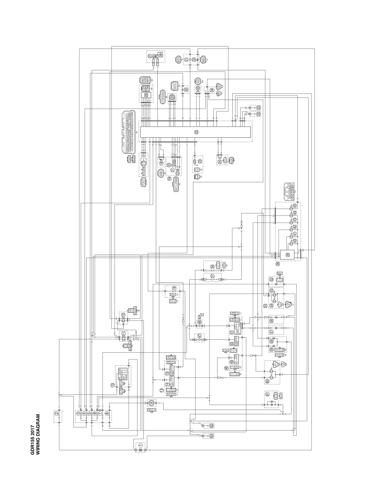
GDR155 2017 WIRING DIAGRAM --- **Main Components & Subsystems:** * **BATTERY** * Connected to STARTING MOTOR and Fuse Box ②. * **STARTING MOTOR** * Connected to BATTERY and component ④. * **Component ② (FUSE BOX)** * FUSE 5A * FUSE 15A * FUSE 10A * FUSE 10A * FUSE 10A * FUSE 20A * FUSE 10A * **IGNITION COIL** (x4 - implied by connections) * Connected to ECM ⑤. * **INJECTOR** (x4 - implied by connections) * Connected to ECM ⑤. * **OXYGEN SENSOR** * Connected to ECM ⑤. * **THROTTLE BODY** * Connected to ECM ⑤. * **CRANK SHAFT POSITION SENSOR** * Connected to ECM ⑤. * **MAP SENSOR** * Connected to ECM ⑤. * **WATER TEMP. SENSOR** * Connected to ECM ⑤. * **FUEL PUMP** * Connected to ECM ⑤ and other components. * **GENERATOR** * Connected to R/R and other components. * **R/R** (Regulator/Rectifier) * Connected to GENERATOR and other components. * **GEAR POSITION SWITCH** * Connected to ECM ⑤. * **CLUTCH SWITCH** * Connected to ECM ⑤. * **SIDE STAND SWITCH** * Connected to ECM ⑤. * **SPEED SENSOR** * Connected to ECM ⑤. --- **Engine Control Module (ECM) ⑤:** * This is the central control unit, represented by the large multi-pin connector block. * It has numerous inputs and outputs connected to almost all labeled sensors, actuators, and switches. * Visible pin labels include: M, E, VC, B+, ACC, and many numbered pins. * Various wire color codes are used throughout the diagram for connections to the ECM and other components (e.g., B, R, W, L, Y, G, O, P, SB, LG, BR, V, GR, LB, and combinations like R/W, B/W, G/Y, etc.). --- **Other Numbered Components (Unlabeled in Diagram):** * ① * ③ * ④ * ⑥ * ⑦ * ⑧ * ⑨ * ⑩ * ⑪ * ⑫ * ⑬ * ⑭ * ⑮ * ⑯ * ⑰ * ⑱ * ⑲ * ⑳ * ㉑ * ㉒ * ㉓ * ㉔ * ㉕ * ㉖ * ㉗ * ㉘ * ㉙ * ㉚ * ㉛ * ㉜ * ㉝ * ㉞ * ㉟ * ㊱ * ㊲ * ㊳ * ㊴ * ㊵ * ㊶ * ㊷ * ㊸ * ㊹ * ㊺ * ㊻ * ㊼ * ㊽ * ㊾ * ㊿ * 51 * 52 * 53 * 54 * 55 * 56 * 57 * 58 * 59 * 60